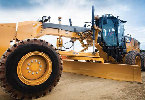
We offer hundreds of cutting edge options, plus customization through our Made as Order (MAO) program. The Cat GraderBits™ system meet the toughest application needs and are complemented by multiple End Bit options.
MOTOR GRADER CUTTING EDGE OPTIONS
PARTNER WITH CATERPILLAR, EDGE OUT THE COMPETITION.
Caterpillar offers a wide range of cutting edges for motor graders. Each provides certain benefits when used in the appropriate application. Using the right edge is critical for enhancing production and keeping total costs to a minimum. The three factors to consider in choosing a cutting edge are shape, width and thickness.
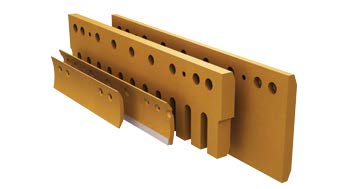
There are two basic edge shapes—flat and curved—with serrated edges available in both configurations. In addition, the Cat GraderBits system dramatically expands the range of edge shape options. Cat offers two types of grader edges and three edge thicknesses for the 16M and 24M motor graders.
| Name | Description |
|---|---|
| SUPERIOR DURABILITY, MORE OPTIONS | Cat DH-2 through-hardened steel edges are available in a variety of shapes and thicknesses to fit every application. |
| EXTENDED EDGE LIFE | Maximize your edge life with tungsten carbide edges. |
| MAXIMUM PENETRATION, MINIMUM WASTE | Cutting bit systems. |
CHOOSING AN EDGE
Edge selection is critical for enhancing production and keeping cost to a minimum. Application affects the cutting edge shape, metallurgy and style. Impact, penetration and abrasion define your application environment. An edge has to penetrate the material and not break during operation. Edge life then becomes a matter of metallurgy and thickness.
WHAT IS YOUR APPLICATION?
| Image | Description |
|---|---|
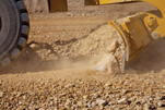 | DEVELOPING A ROAD OR PERFORMING HEAVY MAINTENANCE » A flat edge is best suited for this application. A better penetrating option is a flat serrated edge. A flat edge has limited ability to carry material forward. |
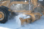 | GRADING HARD-PACKED GRAVEL, FROZEN EARTH AND ICE » A serrated edge penetrates better than a continuous edge because it exerts more down pressure. A curved serrated edge penetrates better than a flat serrated edge with a forward mold board. |
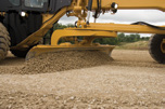 | RECONDITIONING OR FINISH GRADING AN EXISTING ROAD SURFACE » Curved edges penetrate the roadway while carrying existing material forward to leave a smooth flat surface. A better penetrating option is a curved serrated edge. A serrated edge will not leave as clean a roadway surface as a continuous edge. |
THROUGH-HARDENED CUTTING EDGES
Most Cat edges are through-hardened steel, which offers high-impact resistance. High-carbon edges have good surface hardness and perform well in high-abrasion, low-impact applications such as finish work. High-carbon edges will not withstand the impact level of a through-hardened edge.
| Image | Description |
|---|---|
 | FLAT » Heavy road maintenance and pioneering » Maximum strength and available wear material » Best option for abrasion and impact resistance |
 | FLAT SERRATED » Better penetration than a continuous edge (greater down pressure per inch of edge contact) » Designed to penetrate packed gravel, frozen earth and ice » For severe impact conditions, install over a 6" (152 mm) edge to reduce tooth breakage |
 | CURVED » Provides superior penetration and rolling action necessary for fine grading and finish work » Finishing tolerances less than 1/4" (6 mm)—the best value may be in selecting a narrow and thin cutting edge |
 | CURVED SERRATED » A curved serrated edge penetrates better than a straight serrated edge with a forward mold board |
 | EDGE WIDTH EQUALS WEAR MATERIAL » An 8" (203 mm) edge provides twice the wear material as a 6" (152 mm) edge at about 35% more cost » Hardware cost and R&I downtime are reduced by 50% |
TUNGSTEN CARBIDE TILE CUTTING EDGES
Cat Tungsten Carbide Cutting Edges combine through-hardened steel with the wear resistance of tungsten carbide. When used in high-abrasion, low-impact applications, they can provide up to 20 times the life of a standard through-hardened edge. Fewer edge changes means less downtime and lower hardware costs.
| Image | Description |
|---|---|
 | TUNGSTEN CARBIDE EDGES » Tungsten carbide edges have a continuous row of trapezoid-shaped carbide “tiles." This patented shape forms a leading / cutting edge » Carbide tile bottom must be flat to the ground. 20° maximum tilt » Max 5 mph/8kph » Do not use on roads with large embedded rocks |
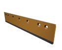 | FLAT EDGES » Maximum strength and available wear material » Longest wearing edge available in high abrasion and low impact |
 | CURVED EDGES » Curved-edge design improves penetration and rolling action » Trapezoid-shaped tungsten carbide tile on leading edge stays sharp as it wears » Shorter edge sections speed rotation and reduce “throw-away" due to edge crowning |
 | SERRATED EDGES » Better penetration than a continuous edge (greater down pressure per in of edge contact) » No cast angle restrictions |
TUNGSTEN CARBIDE INSERT CUTTING EDGES
Cat carbide insert edges offer long wear life in higher speed applications like state/county road snow removal. The tungsten carbide is brazed into a milled groove in the center of the edge. The design offers impact resistance and minimizes edge “crowning" in applications that require a level grading operation.

GRADERBIT SYSTEM
SMOOTH OUT THE TOUGHEST ROADWAYS IN A SINGLE PASS.
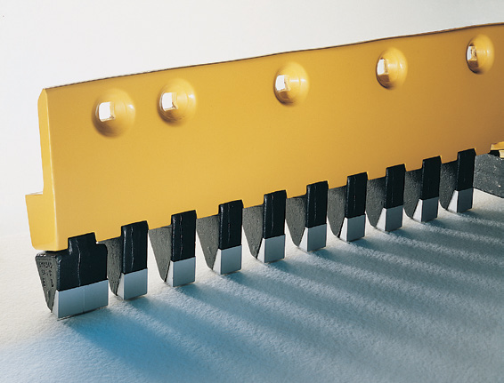
The Cat GraderBit edge system outperforms steel blades in high-production road reconditioning applications. Individual cutting bits are faced with tungsten carbide to form a serrated edge to penetrate and lift material to the surface immediately. As a result, most road maintenance jobs can be accomplished in a single pass.
| Name | Description |
|---|---|
| MORE PRODUCTION, LESS WASTE | Cuts through tough and compact materials, causing lower ripping resistance and less horsepower loss. |
| CUSTOMIZABLE | Create edge patterns that deliver optimum performance. |
| LONGER LIFE | Up to 10x more wear life than a 10" edge. |
INSTALLATION & REMOVAL
Operators can install the entire system in about an hour and field-replace individual bits in minutes without removing the moldboard. Varying bit widths allow you to create both serrated and continuous edge configurations. GraderBits do not require daily inspection like rotating bit systems.
| Image | Description |
|---|---|
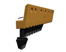 | 1. Bit insertion into adapter board. |
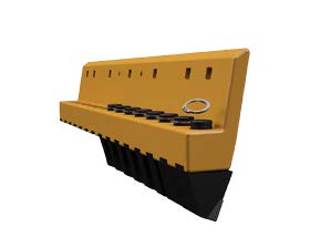 | 2. GraderBits are held in place with a snap ring. |
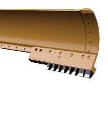 | 3. Adapter boards bolt up to the moldboard like standard edges. |
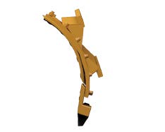 | 4. Keep bits perpendicular to the road surface. The cast angle is not to exceed 10°, penetration depth 11/2“ max, max 6 mph/10kph. |
GRADERBIT SYSTEM
GraderBit adapter board options are 3' (914mm) and 4' (1219mm) sections. Two holespacing patterns are available to control aggregate flow. Standard boards are used for most roadways, and the mining board hold pattern is 50% wider to accommodate large aggregate in mine environments.
.
| Image | Description |
|---|---|
 | STANDARD BITS » Baseline bit - 30mm wide » Moderate penetration » Standard Board Bit Gap: 32mm » Mining Board Bit Gap: 48mm |
 | PENETRATION BITS » Narrower than standard bit - 23 mm wide » Wider gap allows larger aggregate to flow through » Standard Board Bit Gap: 40mm » Mining Board Bit Gap: 55mm |
 | SHARP BITS » 50% narrower than the standard bit - 15.5 mm wide » Allows larger aggregate to flow through » Standard Board Bit Gap: 45mm » Mining Board Bit Gap: 62mm |
 | WIDE BITS » Can configure as a continuous edge » Twice as wide as the standard bit (60 mm) » Standard Board Bit Gap: 3mm » Mining Board Bit Gap: 18mm |
 | MIX AND MATCH » Mix and match bits to control the size of the aggregate left behind » Use wide bits on the end of the moldboard to prevent excessive wear |
MINING BIT SYSTEM
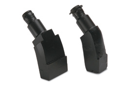
The Mining Bit System works like the GraderBit system, but is upgraded to withstand the extreme applications faced by large motor graders (16M and 24M).
| Name | Description |
|---|---|
| DOUBLE CARBIDE, NO RESTRICTIONS | Protects the face and bottom of the bit, eliminating vast angle restrictions. |
| INTEGRATED DESIGN | Bit profile helps maintain proper grading angle. |
ROTATING BIT SYSTEM
The rotating bit system outperforms steel blades in high-production road reconditioning applications. Individual cutting bits have tungsten carbide tips and form a serrated edge to penetrate and lift material to the surface immediately. As a result, most road maintenance jobs can be accomplished in a single pass.
.

| Name | Description |
|---|---|
| MORE PRODUCTION, LESS WASTE | Material is brought to the surface for reuse, reducing the expense of spreading new gravel. |
| NO RESTRICTIONS | No cast angle restriction. |
| EASY INSTALLATION & MAINTENANCE | Bits changed individually with no special tools. |
ROTATING BIT SYSTEM
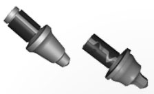
Rotating Scarifier Bits are self-sharpening for more uniform wear and long life. Cutting height is maintained as cutting tools may be rotated from position to position. Carbide bits can last as long as 5 -10 sets of conventional grader blades.
Rotating Scarifier Bits are made for applications such as dirt and gravel reclamation, oil road reclamation, and snow and ice removal.
| Image | Description |
|---|---|
 | 1” SHANK 7/8” SHANK |
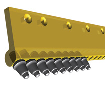 | ADAPTER BOARDS » Either 5/8” or 3/4” bolt hole punch » 3‘ (914mm)-21 bits » 4’ (1219mm)-28 bits » Standard Board uses 7/8” bit » Heavy Duty board uses 1” bit |
 | OPERATING TIPS » 20° Board Angle » Moldboard may vibrate and bits may not turn if angle is not correct |
INSTALLATION & REMOVAL
Improve safety and simplify edge change-out. Cat cutting edges allow you to use a threaded bolt and link to remove and install sections. Even worn edges can be removed, because the threads are located in the back half of the hole.
| Image | Description |
|---|---|
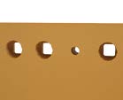 | 1. Drilled and tapped holes. |
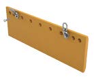 | 2. Attach approved lifting device. |
 | 3. Lift. |

OPERATING TECHNIQUES FOR REDUCED COST.
Through better management of the interface between machine and materials, operators can maximize productivity, lower machine operating costs and reduce cab vibration, improving operator comfort.
| Image | Description |
|---|---|
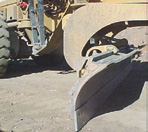 | MOLDBOARD POSITION » Start with moldboard 2” (4“ for 24M) ahead of the edge » Grade with cutting edge 90° to the road » Maintain fixed angle to ensure constant edge thickness » Laid back reduces penetration and can wear moldboard » Frequent angle changes will shorten the edge life |
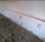 | SPEED AND EXCESSIVE DOWN PRESSURE » Use accumulator to absorb shocks » < 6mph/8kph speed » Excess speed can cause edge slivering » Need penetration? Choose a thinner edge, a serrated edge or the Cat GraderBits system for the most compacted materials |
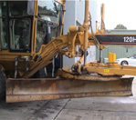 | CROWNING » Occurs when the cutting edge conforms to the material being graded » A narrow and thin edge reduces the “throw away” material » Extreme crowning may require a bit system |
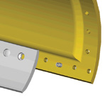 | STANDARDIZE YOUR HARDWARE » Moldboard bushings reduce 3/4” holes to 5/8” » Simplify inventory and lower cost |
PUT AN END TO MOLDBOARD WEAR.
Made of through-hardened DH-2 steel for added strength and service life, Cat end bits protect moldboard edges from wear.
Maximize moldboard life and lower repair costs. Use Cat end bits, overlays, repair plates and hardware to protect and repair your moldboards and working edges.
| Image | Description |
|---|---|
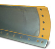 | MOLDBOARD END BITS » Recommended for all applications » Made of through-hardened DH-2 steel for added strength and service life |
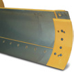 | OVERLAY END BITS » Fit over existing end bit » Recommended for applications such as ditching » Add strength and limit corner wear » When worn on one side, overlay end bits can be rotated for a second wear life |
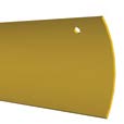 | MOLDBOARD REPAIR PLATES » Extend moldboard life with Cat Moldboard Repair Plates » Routine monitoring and timely edge replacement can prevent damage » When repair is needed, repair plates provide a way to extend moldboard life |
 | HARDWARE » When replacing ground engaging tools, always use Cat hardware regardless of the application » Cat Grade 8 hardware is performance-matched to Cat G.E.T. in both strength and durability |
RIPPER-SCARIFIER SYSTEM
GET MORE OUT OF YOUR GRADER.
Scarifier and ripper systems on motor graders can be used to improve road surfaces by lifting material from compacted and worn areas or by removing the “crowning” that causes excessive wear on cutting edges.

| Description | |
|---|---|
| ENHANCE PRODUCTION | » Loosen material to reduce grading time and fill voids while saving on edge wear. |
| EXTEND VERSATILITY | » Reduce need for dozer ripping or cutting bit systems. |
RIPPER-SCARIFIER COMPONENTS
Scarifiers can be mounted before the blade (V-Block design) or behind the machine (Straight Block design). Rear-mounted ripper-scarifiers are more versatile than forward-mounted configurations. Rip or scarify by changing shank position.
| Image | Description |
|---|---|
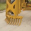 | V-BLOCK » Loosen compacted surfaces, rocky subgrades and frozen ground » Fit ahead of the blade (mid mount) » Holds up to 11 shanks and scarifies up to 46” (1168 mm) wide |
 | STRAIGHT BLOCK » Low-impact applications and shallow scarifying » Higher allowable speed (up to 3rd gear) in shallow » Holds up to 17 shanks and scarifies up to 72” (1828 mm) wide » May be used as a mid-mount scarifier |
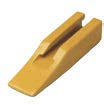 | SCARIFIER TIPS » We offer three types of scarifier tips for surface reconditioning. Tip has a tapered design that secures it to the shank » Through-hardened tips for general purpose scarifying » Heavy-Duty for deep penetration and extended distances » A.R.M. for high-abrasion/low-impact conditions extends tip life 3 to 5 times over through-hardened |
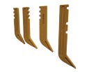 | SCARIFIER SHANKS |
R SERIES RIPPER TIP OPTIONS
Caterpillar offers three options for the R350 ripper tip size class for 16M and 24M motor graders. Due to the extreme nature of maintaining haul roads, scarifiers are not offered on 16M and 24M.
| Image | Description | Option |
|---|---|---|
 | CENTERLINE tips have equal wear material on both sides and can be reversed, which can extend the life and help maintain sharpness. | A.R.M. |
 | PENETRATION ripper tips have an aggressive angle to break through even the hardest surfaces and dig into the ground more effectively. | A.R.M. |
 | PENETRATION - SHARP tips are an intermediate length. They come factory sharpened to ensure maximum penetration. |
INSTALLATION & REMOVAL
The R Series Tooth system uses the standard pin and retainer system. The Tooth Pin Remover tool is available to make removal easier.
| Image | Description |
|---|---|
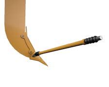 | 1. Place the tool on the tip and align the extractor with the pin. |
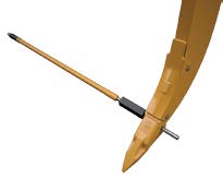 | 2. Strike the tool with a hammer until the pin is removed. |

APROVEITE ESTAS TECNOLOGIAS PARA MELHORAR A PRODUTIVIDADE E RENTABILIDADE DA SUA APLICAÇÃO.


